#13 Buzz Wire Game Project With PicoBricks
You must have heard the expression that computers work with 0s and 1s. 0 represents the absence of electricity and 1 represents its presence. 0 and 1’s combine to form meaningful data. In electronic systems, 0s and 1s can be used to directly control the system. Is the door closed or not? Is the light on or off? Is the irrigation system on or not? In order to obtain such information, a status check is carried out.
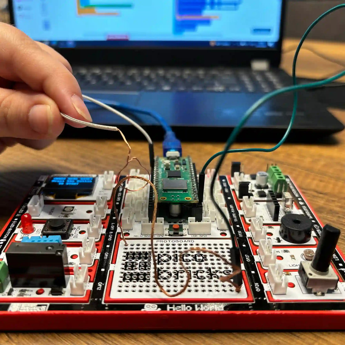
In this project, we will electronically make an attention and concentration developer Buzz Wire Game. It will use a conductor wire, the buzzer, and the LED module with PicoBricks. While preparing this project, you will learn an input technique that is not a button but will be used like a button.
Details and Algorithm
The objective of the game is to move a cable looped around another one, without touching it.
Due to the conductivity of the cables, when they touch each other, they will close the circuit and cause a sound to be emitted.
The player will be asked to press the button to start the game. We reset the timer after the user presses the button.
Then we will set the conductor wire connected to the GPIO1 pin to HIGH status. One end of the cable held by the player will be connected to the GND pin on the PicoBricks. If the player touches the jumper cable in his hand to the conductive wire, the GPIO1 pin will ground and drop to LOW status. PicoBricks will detect this and give an audible and written warning.
Then, it will announce that the game is over, and there will be feedback with light, text, and audio. The elapsed time will be shown on the OLED screen in milliseconds. After 5 seconds, the player will be prompted to press the button to restart.
Components
Wiring Diagram

Along with the PicoBricks base kit,
1: 2 20 cm male-male jumper cables. One end of the cable to be attached to the GND will be stripped 4-5 cm and made into a ring.
2: 15-20 cm conductive wire with a thickness of 0.8 mm. Prepare your materials.

Bend the conductor wire on the protoboard as you wish and pass it through the holes, before passing one end, you must pass the male end, which is connected to the GND pin on the PicoBoard, the other end of the cable you have made into a ring.
3: Conductor Wire
4: Jumper cable with one end connected to the GND pin with a looped end.


5: One end of the jumper cable, which has both male ends, into the hole right next to the end of the conductive wire you placed on the protoboard
6: Twist the end of the jumper wire and the end of the conductor wire together under the protoboard.
7: Bend the other end of the conductor wire placed on the protoboard so that it does not come out.


8: Connect the other male end of the jumper cable that you wrapped around the end of the conductor wire in step 6 to the pin no. GPIO1 on the Picoboard

If you have completed the installation, you can start the game after installing the code. Have fun.
MicroBlocks Codes of the PicoBricks

You can access the Microblocks codes of the project by dragging the image to the Microblocks Run tab or click the button.
MicroPython Codes of the PicoBricks
from machine import Pin, I2C, Timer #to access the hardware on the pico
from picobricks import SSD1306_I2C #OLED Screen Library
from utime import sleep # time library

#OLED Screen Settings
WIDTH  = 128
HEIGHT = 64

sda=machine.Pin(4)#initialize digital pin 4 and 5 as an OUTPUT for OLED Communication
scl=machine.Pin(5)
i2c=machine.I2C(0,sda=sda, scl=scl, freq=1000000)
oled = SSD1306_I2C(WIDTH, HEIGHT, i2c)

wire=Pin(1,Pin.OUT)#initialize digital pin 1 as an OUTPUT
led = Pin(7,Pin.OUT)#initialize digital pin 7 and 5 as an OUTPUT for LED
buzzer=Pin(20, Pin.OUT)#initialize digital pin 20 as an OUTPUT for Buzzer
button=Pin(10,Pin.IN,Pin.PULL_DOWN)#initialize digital pin 10 as an INPUT for button
endtime=0


while True:
    led.low()
    oled.fill(0)
    oled.show()
    oled.text("<BUZZ WIRE GAME>",0,0)
    oled.text("Press the button",0,17)
    oled.text("TO START!",25,35)
    oled.show()
    #When button is '0', OLED says 'GAME STARTED'
    while button.value()==0:
        print("press the button")
    oled.fill(0)
    oled.show()
    oled.text("GAME",25,35)
    oled.text("STARTED",25,45)
    oled.show()
    wire.high()
    timer_start=utime.ticks_ms()
     #When wire is '1', OLED says 'GAME OVER'
    while wire.value()==1:
        print("Started")
    endtime=utime.ticks_diff(utime.ticks_ms(), timer_start)
    print(endtime)
    oled.fill(0)
    oled.show()
    oled.text("GAME OVER!",25,35)
    oled.text(endtime + "ms" ,25,45)
    oled.show()
    led.high()#LED On
    buzzer.high()#Buzzer On
    sleep(5)#Delay
Arduino C Codes of the PicoBricks
#include <Wire.h>
#include "ACROBOTIC_SSD1306.h"

int Time=0;
unsigned long Old_Time=0;

void setup() {
  // put your setup code here, to run once:
  pinMode(20,OUTPUT);
  pinMode(7,OUTPUT);
  pinMode(1,OUTPUT);
  pinMode(10,INPUT);

  Wire.begin();
  oled.init();
  oled.clearDisplay();

#if defined(__AVR_ATtiny85__) && (F_CPU == 16000000)
  clock_prescale_set(clock_div_1);
#endif


}

void loop() {
  // put your main code here, to run repeatedly:
  digitalWrite(7,LOW);

  oled.setTextXY(2,1);
  oled.putString("BUZZ WIRE GAME");
  oled.setTextXY(4,2);
  oled.putString("Press Button");
  oled.setTextXY(5,3);
  oled.putString("TO START!");

  while (!(digitalRead(10)==1)){

  }

  oled.clearDisplay();
  oled.setTextXY(3,6);
  oled.putString("GAME");
  oled.setTextXY(5,4);
  oled.putString("STARTED");

  digitalWrite(1,HIGH);
  Old_Time=millis();

  while(!(digitalRead(1)==0)){

    Time=millis()-Old_Time;
  }

  String(String_Time)=String(Time);

  oled.clearDisplay();
  oled.setTextXY(3,4);
  oled.putString("GAME OVER");
  oled.setTextXY(5,4);
  oled.putString(String_Time);
  oled.setTextXY(5,10);
  oled.putString("ms");

  digitalWrite(7,HIGH);
  digitalWrite(20,HIGH);
  delay(500);
  digitalWrite(20,LOW);
  delay(5000);

  Time=0;
  Old_Time=0;
  oled.clearDisplay();


}