

- Choosing a selection results in a full page refresh.


Couldn't load pickup availability
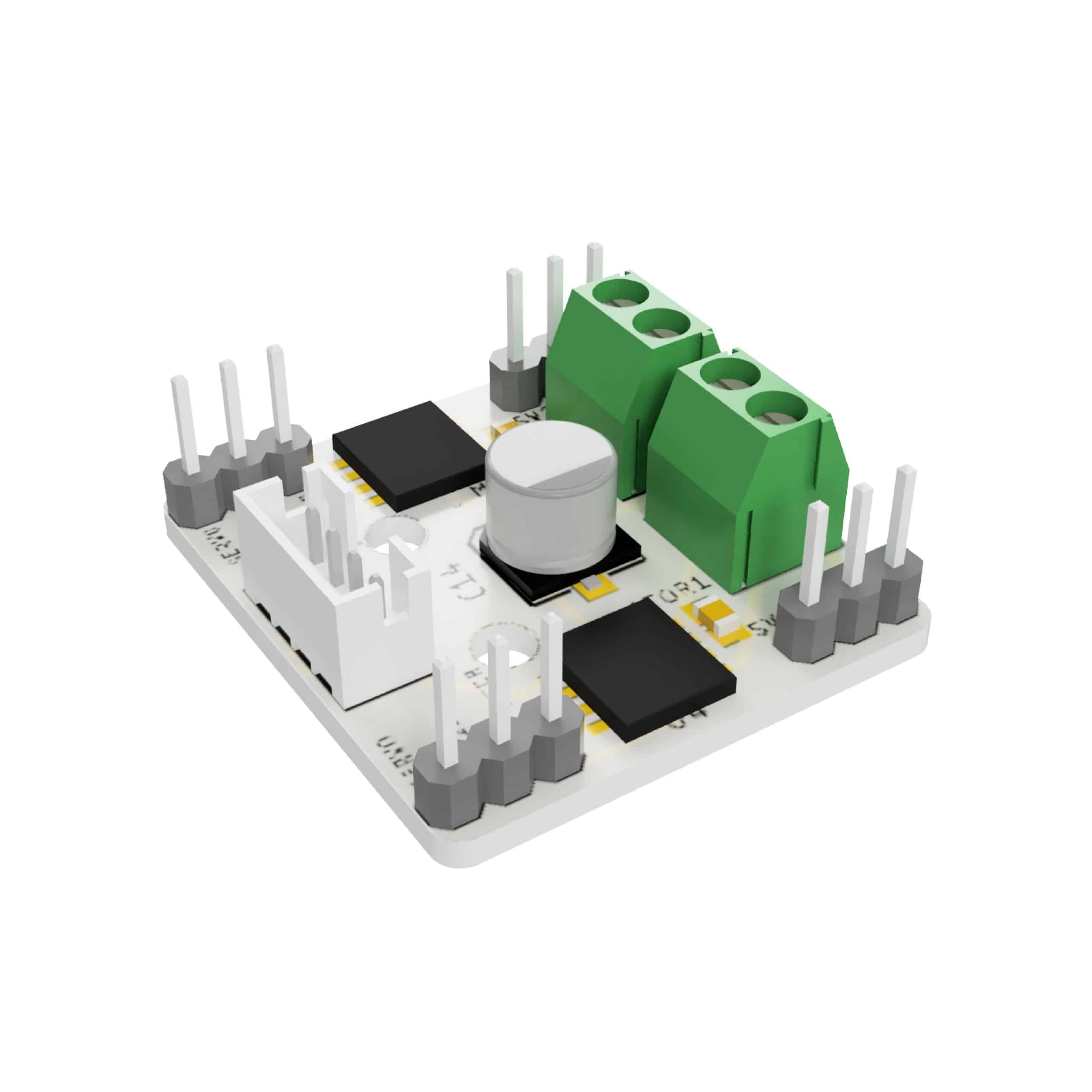
L9110 Motor Control Driver is a dual channel motor driver controller board, which can control two DC motors, or a single four-wire two-phase stepper motor.
The circuit uses the L9110 integrated circuits (IC), which consist of H-Bridge drivers.
The L9110S IC has TTL / CMOS compatible I/O, which interfaces with Arduino and Raspberry Pi computer boards. A minimum of 2.5 V is required to represent a high logic at the inputs IA and IB.
The voltage that you provide to power the IC is the same as that which powers the motor. Hence, this IC operates on a wide supply range (Vcc) from 2.5 V to 12 V. If you were to be using 6 V motors, then obviously, that is the voltage to provide the IC.
This IC provides up to 800 mA continuous drives current to drive a load, however it does not have a heatsink, making it more suitable for low power loads.
L9110 The ASIC device control and drive motor design two-channel push-pull power amplifier discrete circuits integrated into a monolithic IC, peripheral devices and reduce the cost, improve the reliability of the whole. This chip has two TTL / CMOS compatible with the level of the input, with good resistance; two output terminals can directly forward and reverse movement of the drive motor, it has a large current driving capability, each channel through 750 ~ 800mA of continuous current, peak current capability up to 1.5 ~ 2.0A; while it has a low output saturation voltage; built-in clamp diode reverse the impact of the current release inductive load it in the drive relays, DC motors, stepper motor or switch power tube use on safe and reliable. L9110 is widely used in toy car motor drives, stepper motor drive and switching power tube circuit
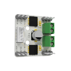
This is a very compact dual channel H-bridge motor driver module. The module incorporates two L9110S H-bridge driver IC’s to allow either one Stepper Motor or two DC Motors to be independently controlled each drive up 800mA of continuous current. The motors are attached via two sets of screw terminals.
The module can accept a supply voltage between 2.5 to 12V allowing for motors within this supply. The voltage range enables this module to be used with both 3.3V and 5V microcontrollers, perfect to be used with an Arduino and robot chassis. A set of female header pins is used to connect this module to a microcontroller.
A PWM Pulse Width Modulation signal is used to control the speed of a motor and a digital output is used to change its direction. This module can also be used to drive a single four line two phase stepper motor. Four holes make this board easy to mount onto your robot or other project. PCB Size: 29.2mm x 23mm
Thanks for subscribing!
This email has been registered!

Edit Option
Back In Stock Notification
Compare
| Product | SKU | Rating | Description | Collection | Availability | Product Type | Other Details |
|---|