Skip to content
International Shipping
Wish Lists Cart
0 items

#17 Two Axis Robot Arm Project With PicoBricks

11 Nov 2023
#17 Two Axis Robot Arm Project With PicoBricks

Robot arms have replaced human power in the industrial field. In factories, robotic arms undertake the tasks of carrying and turning loads of weights and sizes that cannot be carried by a human. Being able to be positioned with a precision of one thousandth of a millimeter is above the sensitivity that a human hand can exhibit. When you watch the production videos of automobile factories, you will see how vital the robot arms are. The reason why they are called robots is that they can be programmed to do the same work with endless repetitions. The reason why it is called an arm is because it has an articulated structure like our arms. How many different directions a robot arm can rotate and move is expressed as axes. Robot arms are also used for carving and shaping aluminum and various metals. These devices, which are referred to as 7-axis CNC Routers, can shape metals like a sculptor shapes mud.

Depending on the robot arm’s purpose, stepper motors and servo motors can be  used. PicoBricks allows you to make projects with servo motors. 

Details and Algorithm

When an object is detected on the LDR sensor, RGB LED will turn RED and the robot arm will execute the following maneuvers:

  • open the gripper
  • move downwards
  • close the gripper
  • move upwards

At the completion of the arm movement, the RGB LED will turn  GREEN.

Based on these motions, the initial positions of the two servos should be as such:

  • Servo1 controlling gripper should be in CLOSED position
  • Servo 2 controlling up/down movement should be in UP position

Four different motion control logic is needed:

  • UP: execute a 90 degree movement in 2 degree increments
  • DOWN: execute a 90 degree movement in -2 degree increments
  • OPEN: position gripper to 90 degrees
  • CLOSE: position gripper to -60 degrees

All movements will be accompanied by sound feedback and displayed on the IDE for troubleshooting purposes. Later you can remove the say blocks, if desired.

Servo motor movements are very fast. In order to slow down the movement, we will move the servo motors 2 degrees at a time at 30 millisecond intervals, to complete a 90 degree motion. We’re not going to do this for the gripper to close.

3D Print and assemble the necessary parts for the Gripper from the link here.

Components

1X PicoBricks
2X Servo Motor
4X Easy connection Cables
Jumper Cables

Wiring Diagram

You can code and run Picobricks’ modules without wiring. If you are going to use the modules by separating them from the board, you should make the module connections with grove cables.

Construction Stages of the Project

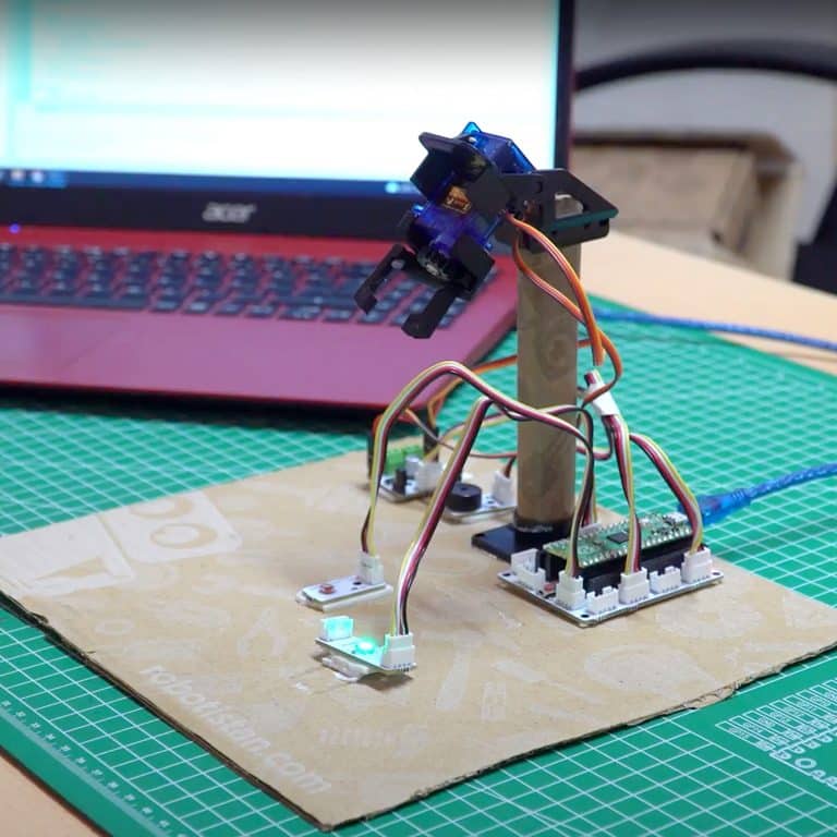
Prepare the parts of the Pan-Tilt kit to prepare the project. Carry your 3D printed parts, waste cardboard pieces, hot silicone glue and scissors with you.

1) First of all, we will prepare the fixed arm of the robot arm. Make an 8 cm high cardboard cylinder into the rounded part of part D. Place it on the D part and attach or glue it with silicone.

2) Place the head that came out of the servo motor package on the C part by shortening it a little. Fix with the smallest screws from the Pan Tilt kit.


two axis robot arm with rasperry pi


3) Fix parts A and C together with 2 pointed screws.

4) Internally attach the servo motor to part C. Then place the servo motor on part B and screw it.

5) For the holder, cut one of the servo motor heads in the middle of the gear part that you printed on the 3D printer and place it into the gear. Then screw it to the servo motor.

6) Adhere together the 3D printed Linear gear and the handle with strong adhesive.

7) Place the servo in the 3D print holder and fix it. You can do this with hot silicone or by screwing. When placing the servo gear on the linear gear, make sure it is fully open.

8) Attach the holding servo system to part B with silicone.

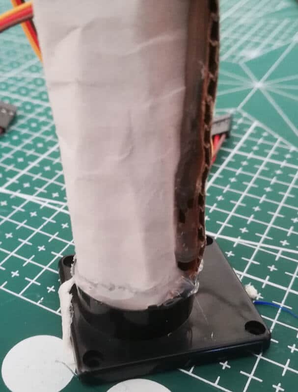
9) Pass the piece we prepared in step 3 over the cylinder we prepared from cardboard in the first step and fix it with silicone.

10) Put the motor drive jumpers on the Servo pins. Connect the cable of the holding servo to the GPIO21 and the cable of the tilting servo to the GPIO22.

11) Place the motor driver, buzzer, LDR and RGB LED module on a platform and place the robot arm on the platform accordingly. With the 3D Pen printer, you can customize your project as you wish.

Microblocks Run Tab


MicroPython Codes of the PicoBricks

Robot Arm Code:


from machine import Pin, PWM, ADC
from utime import sleep
from picobricks import WS2812

# Define libraries
ws = WS2812(6, brightness=0.3)
ldr = ADC(27)
buzzer = PWM(Pin(20, Pin.OUT))
servo1 = PWM(Pin(21))
servo2 = PWM(Pin(22))
# Define LDR, buzzer, and servo motor pins

servo1.freq(50)
servo2.freq(50)
buzzer.freq(440)
# Define frequencies of servo motors and buzzer

# RGB color settings
RED = (255, 0, 0)
GREEN = (0, 255, 0)
BLACK = (0, 0, 0)

angleupdown = 4770
angleupdown2 = 8200

def up():
    global angleupdown
    for i in range(45):
        angleupdown += 76
        servo2.duty_u16(angleupdown)
        sleep(0.03)
    buzzer.duty_u16(2000)
    sleep(0.1)
    buzzer.duty_u16(0)
    # Servo2 goes up at specified intervals

def down():
    global angleupdown
    for i in range(45):
        angleupdown -= 76
        servo2.duty_u16(angleupdown)
        sleep(0.03)
    buzzer.duty_u16(2000)
    sleep(0.1)
    buzzer.duty_u16(0)
    # Servo2 goes down at specified intervals

def open():
    global angleupdown2
    for i in range(45):
        angleupdown2 += 500
        servo1.duty_u16(angleupdown2)
        sleep(0.03)
    buzzer.duty_u16(2000)
    sleep(0.1)
    buzzer.duty_u16(0)
    # Servo1 works for opening the clamps

def close():
    global angleupdown2
    for i in range(45):
        angleupdown2 -= 500
        servo1.duty_u16(angleupdown2)
        sleep(0.03)
    buzzer.duty_u16(2000)
    sleep(0.1)
    buzzer.duty_u16(0)
    # Servo1 works for closing the clamps

open()
servo2.duty_u16(angleupdown)
ws.pixels_fill(BLACK)
ws.pixels_show()

while True:
    if ldr.read_u16() > 20000:
        ws.pixels_fill(RED)
        ws.pixels_show()
        sleep(1)
        buzzer.duty_u16(2000)
        sleep(1)
        buzzer.duty_u16(0)
        open()
        sleep(0.5)
        down()
        sleep(0.5)
        close()
        sleep(0.5)
        up()
        ws.pixels_fill(GREEN)
        ws.pixels_show()
        sleep(0.5)
        # According to the data received from LDR, RGB LED lights red and green and servo motors move

Robot Arm Servo Code:


from machine import Pin, PWM

servo1 = PWM(Pin(21))
servo2 = PWM(Pin(22))

servo1.freq(50)
servo2.freq(50)

servo1.duty_u16(8200) # 180 degree
servo2.duty_u16(4770) # 90 degree

Arduino C Codes of the PicoBricks

#include <Adafruit_NeoPixel.h>
#ifdef __AVR__
  #include <avr/power.h>
#endif
#define PIN 6
#define NUMPIXELS 1
Adafruit_NeoPixel pixels(NUMPIXELS, PIN, NEO_GRB + NEO_KHZ800);
#define DELAYVAL 500 // Time (in milliseconds) to pause between pixels

#include <Servo.h>
Servo myservo1;
Servo myservo2;

int angleupdown;

void setup() {
  pinMode(20, OUTPUT);
  pinMode(27, INPUT); // define input and output pins

  pixels.begin(); // Initialize the NeoPixel library.
  pixels.clear(); // Initialize all pixels to 'off'

  myservo1.attach(21);
  myservo2.attach(22); // Attach the servos.

  Open();
  angleupdown = 180;
  myservo2.write(angleupdown);
}

void loop() {
  if (analogRead(27) > 150) {
    pixels.setPixelColor(0, pixels.Color(255, 0, 0)); // Red color.
    pixels.show();
    delay(1000);
    tone(20, 700); // Sound the buzzer
    delay(1000);
    noTone(20); // Stop the buzzer
    Open();
    delay(500);
    Down();
    delay(500);
    Close();
    delay(500);
    Up();

    pixels.setPixelColor(0, pixels.Color(0, 255, 0)); // Green color.
    pixels.show();
    delay(500);

    // Clear the color after a delay.
    pixels.setPixelColor(0, pixels.Color(0, 0, 0)); // Off
    pixels.show();
    delay(500);
    Open();
    angleupdown = 180;
    myservo2.write(angleupdown); // Reset the servo position
  }
}

void Open() {
  myservo1.write(180); // Servo opens
}

void Close() {
  myservo1.write(30); // Servo closes
}

void Up() {
  for (int i = 0; i < 45; i++) {
    angleupdown += 2;
    myservo2.write(angleupdown); // Move servo up
    delay(30);
  }
}

void Down() {
  for (int i = 0; i < 45; i++) {
    angleupdown -= 2;
    myservo2.write(angleupdown); // Move servo down
    delay(30);
  }
}

GitHub Project Page
Prev Post
Next Post

Thanks for subscribing!

This email has been registered!

Shop the look
Choose Options

Edit Option

Have Questions?

Back In Stock Notification

Compare

Product SKUDescription Collection Availability Product Type Other Details

Terms & Conditions

What is Lorem Ipsum? Lorem Ipsum is simply dummy text of the printing and typesetting industry. Lorem Ipsum has been the industry's standard dummy text ever since the 1500s, when an unknown printer took a galley of type and scrambled it to make a type specimen book. It has survived not only five centuries, but also the leap into electronic typesetting, remaining essentially unchanged. It was popularised in the 1960s with the release of Letraset sheets containing Lorem Ipsum passages, and more recently with desktop publishing software like Aldus PageMaker including versions of Lorem Ipsum. Why do we use it? It is a long established fact that a reader will be distracted by the readable content of a page when looking at its layout. The point of using Lorem Ipsum is that it has a more-or-less normal distribution of letters, as opposed to using 'Content here, content here', making it look like readable English. Many desktop publishing packages and web page editors now use Lorem Ipsum as their default model text, and a search for 'lorem ipsum' will uncover many web sites still in their infancy. Various versions have evolved over the years, sometimes by accident, sometimes on purpose (injected humour and the like).
this is just a warning
Login
Shopping Cart
0 items