RGB LED Lights
Table of Contents
RGB is a color model frequently used in Color Displays and digital imaging technologies. RGB represents the combination of “Red”, “Green” and “Blue” colors. These three basic colors can create other colors when combined with different intensities. The RGB model is used to describe the color of a pixel, with each color representing a value between 0 and 255. Different combinations of these values are used to produce millions of different color tones and play a fundamental role in creating digital images.
This project allows color control with potentiometers using an RGB LED. In this project realized with PicoBricks, three potentiometers control the RGB components (red, green, blue) independently. Each potentiometer adjusts the brightness of the corresponding color component. The project allows you to easily create different colors and shades. The RGB LED’s connections and code are simple and ideal for customizing the project or creating a basic foundation for more complex applications. It offers the ability to change the color of the LED in real time by turning the potentiometers.
The use of RGB LEDs and potentiometers teaches you to control analog and digital input/outputs. It also provides a practical opportunity to improve coding skills. Understanding and customizing the project helps in learning the functioning of electronic circuits and how to use the components. These types of projects are a great starting point for STEM (Science, Technology, Engineering, and Mathematics) education and provide an interesting experience for those who want to improve their electronics and programming skills.
LED technology has transformed lighting, providing limitless options for imaginative and dynamic illumination. In areas such as interior design, entertainment, and daily use, RGB LEDs offer the means to set the ambiance, craft striking visuals, and personalize our surroundings. As we further uncover their potential, it’s evident that RGB LEDs are now fundamental in modern lighting, infusing our lives with color, vitality, and adaptability. With continuous progress in this field, the future promises more thrilling opportunities for RGB LEDs to excel.
If you would like to get more detailed information about RGB LEDs, you can click here!
Details And Algorithm
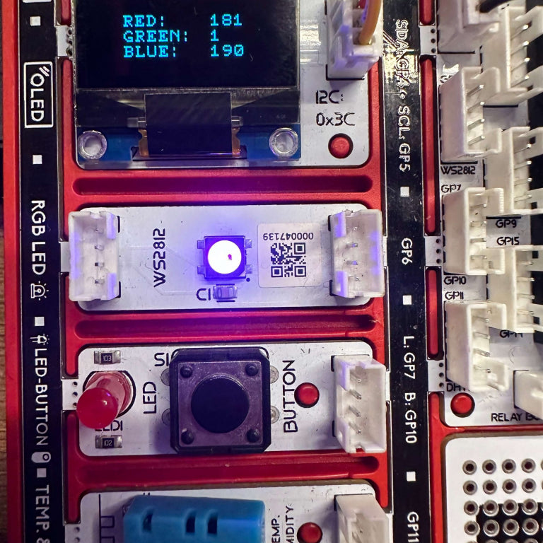
RGB LED control project allows you to customize color combinations by controlling RGB LEDs (red, green, blue) through potentiometers. The first step is to convert the potentiometer’s value from 0 to 1023 to a value from 0 to 255. This transformation is necessary to control the brightness of the color components. Each potentiometer then assigns a value to the red, green, and blue components. In the final step, these values are assigned to the relevant components of the RGB LED to create the desired color and brightness combination. By turning the potentiometer, you can adjust the LED color and brightness in real time.
Component
1X PicoBricks
Wiring Diagram

MicroBlocks Codes of The PicoBricks

MicroPython Codes of The PicoBricks
from time import sleep
from machine import Pin
from picobricks import WS2812
import time
from machine import I2C
from picobricks import SSD1306_I2C
import machine
import math

ws2812 = WS2812(6, brightness = 1)
i2c = I2C(0, scl=Pin(5), sda=Pin(4), freq=200000)
oled = SSD1306_I2C(128, 64, i2c, addr=0x3c)
pin_button = machine.Pin(10, machine.Pin.IN)
import math
pot = machine.ADC(26)

def color_code():
    global pot_val, red, green, blue, color_list, i
    while (pin_button.value()) == (0):
        oled.fill(0)
        pot_val = round(round( pot.read_u16() – 0 ) * ( 255 – 0 ) / ( 65535 – 0 ) + 0)
        oled.text(“{}”.format(str(str(color_list[i])+str(”  “))+str(pot_val)), 0, 0)
        oled.show()

    return pot_val

def chosing_red():
    global pot_val, red, green, blue, color_list, i
    red = color_code()
    i += 1

def chosing_green():
    global pot_val, red, green, blue, color_list, i
    green = color_code()
    i += 1

def chosing_blue():
    global pot_val, red, green, blue, color_list, i
    blue = color_code()
    i += 1

while True:
    color_list = [“RED”, “GREEN”, “BLUE”]
    red = 0
    green = 0
    blue = 0
    i = 0
    ws2812.pixels_fill((0 ,0 ,0 ))
    ws2812.pixels_show()
    oled.text(“{}”.format(“Color Code”), 0, 0)
    oled.text(“{}”.format(str(“RED = “)+str(red)), 20, 25)
    oled.text(“{}”.format(str(“BLUE = “)+str(blue)), 20, 35)
    oled.text(“{}”.format(str(“GREEN = “)+str(green)), 20, 45)
    chosing_red()
    time.sleep((1))
    chosing_green()
    time.sleep((1))
    chosing_blue()
    oled.fill(0)
    oled.show()
    ws2812.pixels_fill((red, green, blue))
    ws2812.pixels_show()
    time.sleep((2))
PicoBricks IDE Codes of The PicoBricks

Arduino C Codes for PicoBricks
#include <Wire.h>
#include "ACROBOTIC_SSD1306.h"
#include <Adafruit_NeoPixel.h>
#define BUTTON_PIN 10
#define LED_PIN 7
#define PIN            6
#define NUMLEDS        1

Adafruit_NeoPixel leds = Adafruit_NeoPixel(NUMLEDS, PIN, NEO_GRB + NEO_KHZ800);
int color_list[0];
int pot_val = 0;
String pot_val_str = " ";
int red = 0;
int green = 0;
int blue = 0;

void color_code(){
  while(digitalRead(BUTTON_PIN) == 0){
    pot_val = analogRead(A0);
    pot_val = map(pot_val,0,1023,0,255);
    oled.setTextXY(0,11);
    oled.putString(String(pot_val));
    Serial.println(pot_val);
  }
}

void setup() {
  Serial.begin(9600);
  Wire.begin();
  oled.init();
  oled.clearDisplay();
  pinMode(BUTTON_PIN, INPUT);
  pinMode(LED_PIN, OUTPUT);
  randomSeed(analogRead(A0));
  leds.begin();
}

void loop() {
  oled.setTextXY(0,0);
  oled.putString("Color Code:");
  oled.setTextXY(1,0);
  oled.putString("----------------");
  oled.setTextXY(2,1);
  oled.putString("RED");
  oled.setTextXY(4,1);
  oled.putString("GREEN");
  oled.setTextXY(6,1);
  oled.putString("BLUE");

  while (digitalRead(BUTTON_PIN) == LOW) {
    color_code();
    digitalWrite(LED_PIN,HIGH);
    delay(1000);
    digitalWrite(LED_PIN,LOW);
    red = pot_val;
    oled.setTextXY(2,7);
    oled.putString(String(red));
    delay(1000);
    color_code();
    digitalWrite(LED_PIN,HIGH);
    delay(1000);
    digitalWrite(LED_PIN,LOW);
    green = pot_val;
    oled.setTextXY(4,7);
    oled.putString(String(green));
    color_code();
    digitalWrite(LED_PIN,HIGH);
    delay(1000);
    digitalWrite(LED_PIN,LOW);
    blue = pot_val;
    oled.setTextXY(6,7);
    oled.putString(String(green));
    digitalWrite(LED_PIN,LOW);
    delay(1000);

    for(int i=0;i < NUMLEDS;i++) {
      leds.setPixelColor(i, leds.Color(red,green,blue));
      leds.show();
      delay(2000);
      leds.setPixelColor(i, leds.Color(0, 0, 0)); //turn all pixels black 'off'
      leds.show();
    }
  }

  oled.clearDisplay();
}


