Table of Contents
Relays are the unsung heroes of the electrical world, quietly working behind the scenes to power countless devices and systems! In this article, we’ll embark on a journey to explore the world of relays, from the basics of what a relay is to how to effectively test and utilize these invaluable components.
Relays Meaning
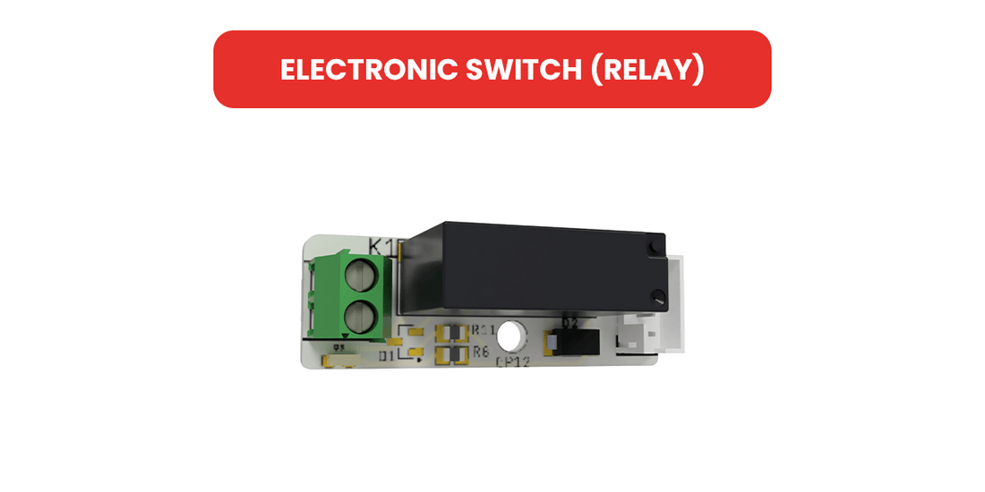
A relay is an electrical switch or device that is designed to control the flow of electrical current between two separate circuits. It acts as a bridge or a mediator, allowing an electrical signal or current to be switched on or off in one circuit by energizing or de-energizing a coil or electromagnet in another circuit.
Relays are commonly used in various electrical and electronic applications to perform tasks such as switching high-voltage loads with a low-voltage control signal, amplifying weak signals, providing isolation between circuits, and allowing for the automation of complex processes.
The basic principle of a relay involves an input (control) circuit and an output (load) circuit. When a voltage or current is applied to the input circuit, it energizes the relay’s coil, creating a magnetic field. This magnetic field then causes the relay’s switch contacts to change their position, either opening (turning off) or closing (turning on) the connection in the output circuit. Relays come in various forms and configurations, including electromagnetic relays, solid-state relays, and reed relays, each suited to specific applications and requirements.
Relays are widely used in industries such as automation, telecommunications, automotive, and control systems, where they play a critical role in ensuring the proper functioning and control of electrical devices and processes.
What is Relay Used For?
A question such as why relay is used may have come to your mind. The electrical function of relays are very important electrical devices widely used to control and switch circuits. They enable a low-power signal or circuit to manage a higher-power one, providing essential isolation and protection. Relays find applications in industrial automation, HVAC systems, automotive electronics, telecommunications, and more. For example, they trigger machinery and processes in automation and start engines and control lights in the automotive industry. Their versatility and capacity to handle high currents and voltages make relays indispensable for the efficient and safe operation of various electrical systems and devices.
How to Test a Relay?
Testing a relay’s functionality is vital. A “relay tester” is a specialized tool that simplifies this process. Connect the relay to the tester, ensuring proper alignment. Activate the tester to apply voltage and test continuity, ensuring accurate and efficient relay assessment. Using a relay tester saves time and ensures reliability in electrical systems.
You can test relay with this Picobricks project: Picobricks Greeting
How to Test Relay with a Multimeter
Testing a relay with a multimeter is simple. Set the multimeter to continuity or resistance mode, find the coil and contact pins labeled as “coil,” “C,” “NO,” and “NC.” Check coil continuity; it should read within the specified range. Apply rated coil voltage; listen for a click as the relay switches. With the coil energized, measure continuity between “C” and “NO”; it should show low resistance, indicating closed contacts. Test “C” and “NC” for continuity; it should display infinite resistance, confirming open NC contacts. This multimeter test ensures the relay works in your circuit.
Relay Diagram
A relay diagram, often used in electrical and electronic schematics, provides a visual representation of how a relay is wired and connected within a circuit. It illustrates the arrangement of the relay’s coil, its contacts (normally open, normally closed, and common), and how it interacts with other components in the circuit. Relay diagrams are essential for understanding and designing complex control systems, as they help visualize how signals and power flow through the relay, allowing engineers and technicians to troubleshoot, analyze, or modify the circuit effectively. These diagrams serve as valuable tools in the world of electronics, ensuring that relays are correctly integrated into various applications, from automation to safety systems.

FAQ
1. Why use relay and fuses?
Relays are used for controlling high power devices with a low power signal, providing isolation between control and high power circuits. Fuses are used for safety, protecting electrical circuits from overcurrent and preventing damage or fire.
2. What is difference between relay and contactor?
The main difference between a relay and a contactor is their power handling capacity. Relays are typically used for lower power applications, while contactors are designed for higher power devices and systems, often in industrial settings. Additionally, contactors usually handle larger current loads and are more robust than relays.
3. Are relays AC or DC?
Relays can be designed for either AC (Alternating Current) or DC (Direct Current) applications. The type of current they are intended to control is determined by their design and the specific needs of the circuit they are used in.
4. Why relay used in motor?
Relays are used in motors to control the high power required to start and run the motor with a low power signal, providing safe and efficient operation while also offering overload protection.


